Used are TinkerCAD website, save / export the .stl file. Then used CURA to slice into .gcode for Ender3_v2 3d printer.
Settings:
Standard Quality, with Layer Height: 0.1 instead of default 0.2 mm slicing
Walls, with Wall Thickness: 1.0 mm instead of 0.8
Material, with Printing temperature: 210 degrees Celsius instead of 200
Flow: 105% instead off 100%
Mesh fixes, with Extension stitching: ON instead off
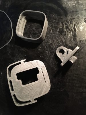
Raspberry Camera Case
From: https://www.thingiverse.com/thing:4761307
And: https://www.thingiverse.com/thing:4721088
A 'cut-through' image:
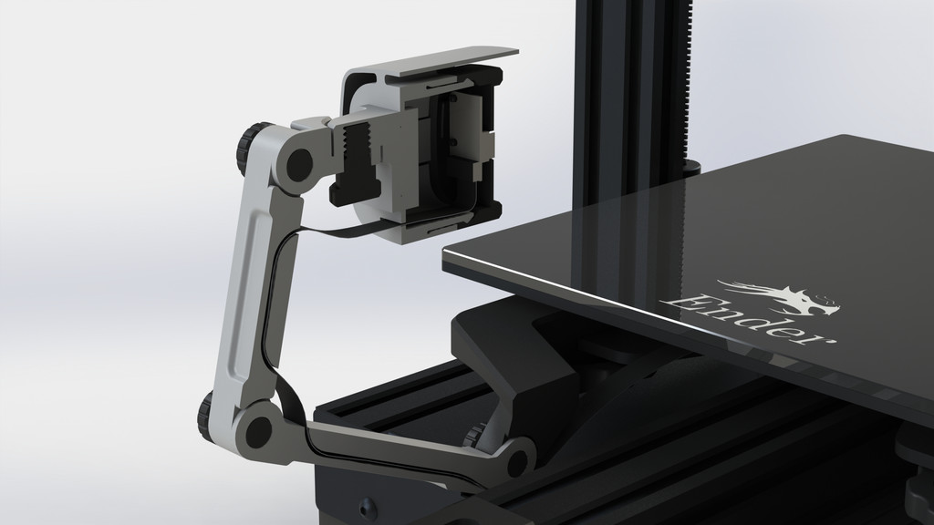
Another nice view of the camera holder itself:
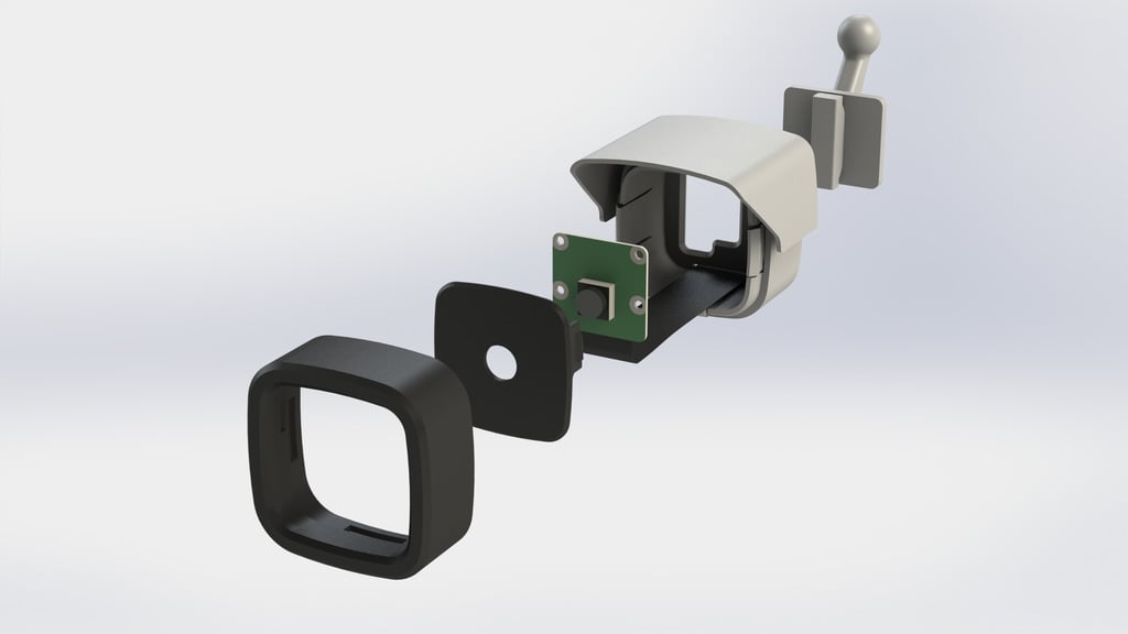
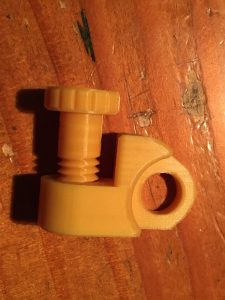
Mounting_Bracket and Bolts:
I find the mounting bracket too big, so made my own Eigen_Mount3 (https://www.tinkercad.com/things/4adMbH ... igenmount3).
And made a special bolt for it, as well as new other bolts, the original (2) bolts have some -very slightly- issues.
A 0.1mm slicing will make a good working bolts of the original ones.
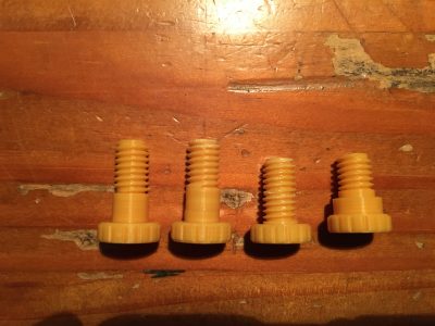
Bolt:
- ISO metric thread
- groundplate = 9.13 x 9.13 mm
- height = 12 mm
- diameter 12
- Pitch 1.5
- Segments = 24
- Rotations = 8
- Tip scanel = 0
- Tip segments = 2
- Thread scale = 1
Added this to the 'default' bolt-knob.
Eigen_MountX has too small thread. It needs a bigger thread to be extracted.
1 or 2 mm bigger?
Also the bold needs an extra winding, its just too short.
Eventually a flatcable pass-through, like the 2 arm-parts? not needed now.
Eigen_Mount3 has bolt raised to 17 x 17 mm to extract from holder. (TO BE TESTED !!!)
Made new bolts: file Long_Bolt_3x_tst2, working
Contains all original and adjusted bolts.
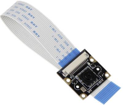
Mounting_Plate, RaspberryPi Camera vs Toy-it Camera
Next found a rather bigger issue with it's mounting_plate, which I call Camera_Plate.
The stand-offs are in wrong position for my Joy-it_Camera.
Photos of wrong stand-offs:
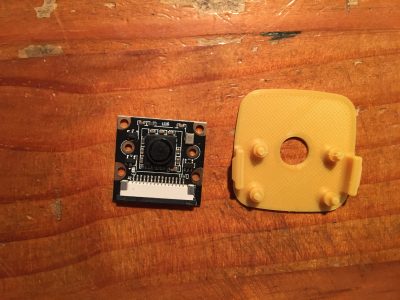
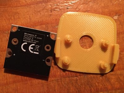
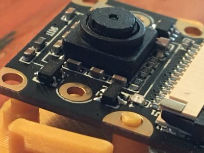
The original is for a RaspberryPi Camera and my Joy-it Camera will not fit.
So within Tinkercad copied / paste and made Camera_Plate_2.
Almost perfect, made Camera_Plate_3 with lens-hole 1mm up, related to stand-offs.
And all stand-offs up in the case (more room for flat-cable).
Left the new Toy-it version, right the RaspberryPi version.
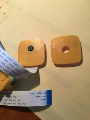
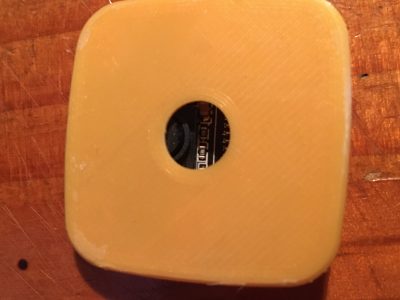
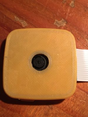
This one works perfectly!
Maybe higher the stand-offs by 1mm (max), to lower the lens in the case.
Lens is now before it's mounting_plate.
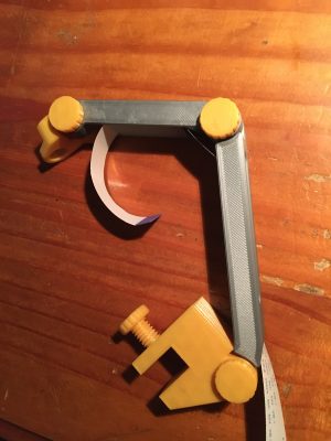
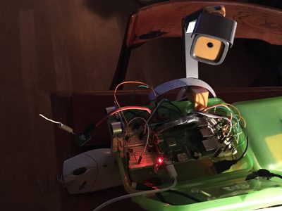
Printed:
- Mid_Arm
- 1 Long_Bolt
- 1 Eigen_Mount3 (small hole, adjusted manually)
- 1 Eigen_Bolt for Eigen_MountX (broken but fixed
- 1 Short_Bolt
- 2 Long_Bolt
- Upper_Arm
- Lower_Arm
- Mounting_Plate (has issues... stand-offs in wrong position). Here called: Camera_Plate_X
- Housing_Rear
- Housing_Front
- Mounting_Bracket_Threaded
10 Hours of printing for the last 3 parts!
But happy with the result.
2 Bolts already broken, these must be made solid, I guess.
Made the 3 long-bolts 100% filled. Set Infill Density to 100% instead of 20%.
Much better and stronger!
Additional made a rounded version of the Eigen_Mount.
And a Camera_Plate(4) with a extra hole for the red LED which is on the Toy-it Camera.
DG.