Raspberry 3B+, RF Light On, Light Off, Dim Light
Posted: 17 Jan 2023, 13:12
Reverse enginering TR-502MSV remote control sender.
Same as Brennenstuhl HS 433.

PCB: TR502A3
Left (white) one is defect, but wana try to control receivers (3 + 1 dimmer) with RPi.
The sender has a MCU kinda blob on its PCB and a second smaller PCB with the transmitter.
So we have no idea which ic-chip is used for this rf-system.
It has a 433MHz oscilator, so this should be possible to re-create.
Button part of sender has 455kHz ceramic oscilator (code) and passes it to 433MHz transmitter.
We made our own halogene remote as exam project 30 years ago, IR-led driven, 455kHz, with Pulse Pause Modulation (PPM), we also want to implement this into new (raspberry) remote?
We'll see if we can arrange that later on.
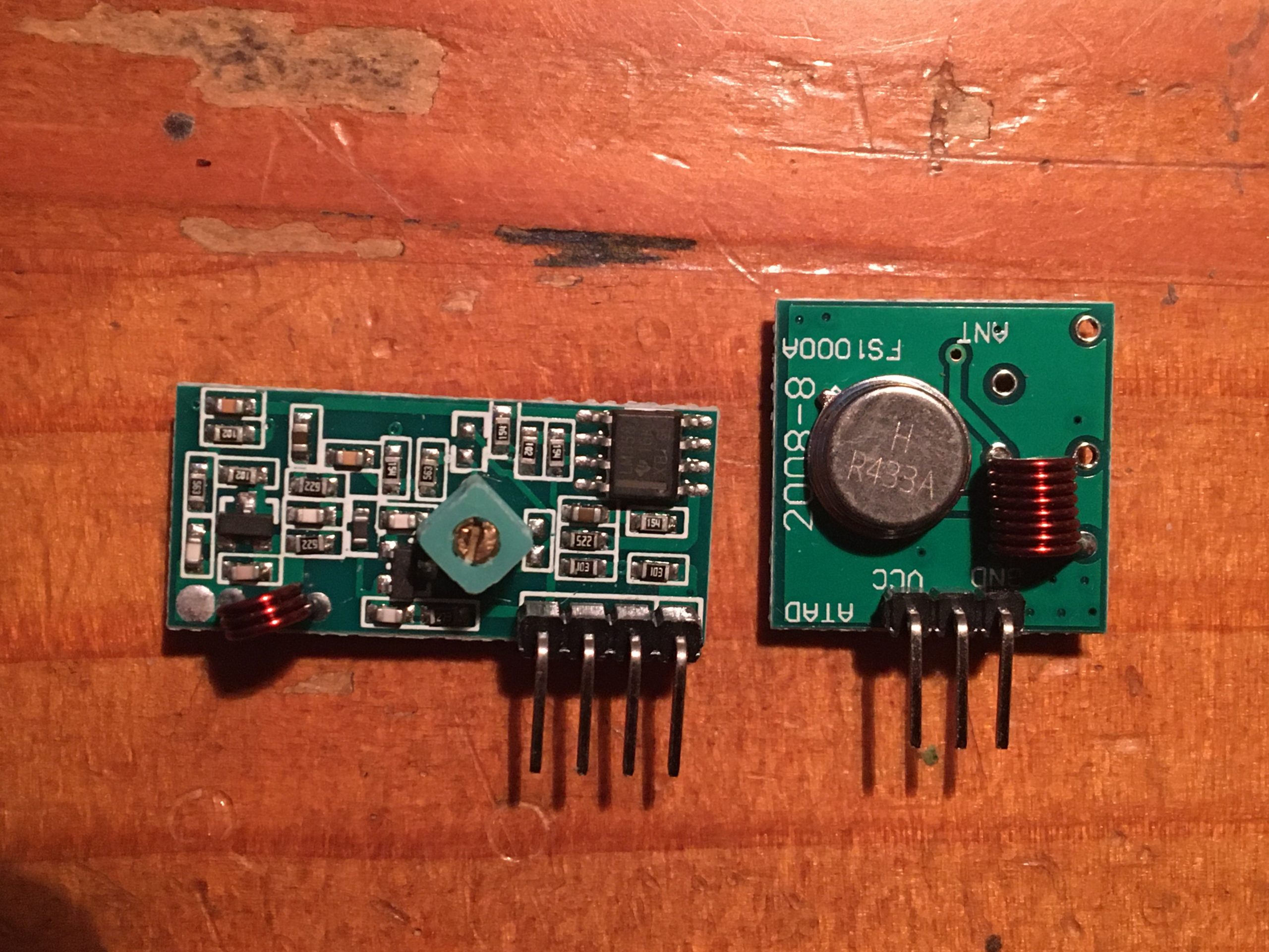
Received the Raspberry/Arduino 433MHz transmitter and receivers.

Also new remote control (Brennestuhl HS 433) for broken sender with even more receivers and dimmers.
We tested all outlet-receivers with the new remote control and working fine.
The new rpi-receiver does work. We see data on scope.
But the raspberry does not recieve any usable data, it's always something else? (noise?)
We tried: RFSniffer, rfscanner?, rpi-rf_receiver & send, but all return no usable data.
Should I use a voltage divider?
Yes, with rfrecorder I've (rf)recorded 1 switch 'on' function, the 'off' still did not work.
We have to analyze the recorded data.
Also for switch1 we found the 'on' data, not the 'off' data...

This is from rpi-rftransmitter, which also include rfscanner.
But with too much noise, rfscanner printing rubbish on screen.
Rewrite in python will be best sollution, i guess.
rfrecorder does check receiver data for 5 times before saving into file.
With this command (and a small voltage divider) I received the 'on' function for SW1 and SW2.
Not (yet) the 'off' functions...
Some code testing....
RFSW2ON: 20230116235953.rfdat
times in usecs
Total is about 112,5 msec, without the last 'off' command (74685usec) it is: 39 msecs
60 bits in 40msec makes about 666 usecs/bit.
We dont want double byte be longer than 1300 usec, so we take 650 as base clock. (Triple bits do NOT exist!)
Now testing own made code:
RFSW1ON
1011 0110 1101 1011 0110 1101 1011 0110 1101 1011 0110 1100 1011 0110 1100 1000
RFSW2ON
1011 0110 1101 1011 0110 1101 1011 0110 1101 1001 0110 1100 1011 0110 0100 1000
Using 650 as base usec for data, 1300 as double bit ...
This is working fine!
Guessing RFSW3ON ?
And guess what? (TF?) It works!
With piscope:
RFSW1ON

RFSW2ON

RFSW3ON

(Not all are set to right '0'-left-position.)
We now will find the 'off' function!
Searching first for SW 4 we found (typically) the OFF function of SW 1, funny.
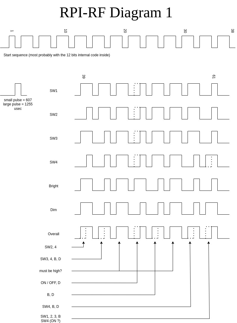
Clearly '10' is the start sequence (or more, but if we stay with that...), we see a '110' pattern.
What if we just sent this 3 bits untill the end?
There we found the OFF for SW 1 !
From here we wont divide into 4 but 3 bits.
1 day later ...
Still not exact the right code (or timing sequence) As we now only struggle with SW 4
SW1, SW2 and SW3 are remote on/off outlets wich now can be controlled by a raspberry (or remote control).
We have to set 1 bit other then SW1, SW2 and SW3, according ON/OFF function.
Our 'selfmade' code is 39 msec long, the 'real' data about 38 msec, but it could be a culprit.
We'll see. My code uses 650 and 1300 usecs for timing the data.
Could be a little less to get to 38msec for full 61 bits.
For now we can do ON/OFF as on the remote for 4 outlet-switches.
We did record all RF data of the OFF switches, with rfrecorder.
Start sending before start recording helps to get the right code. Especially with bad receivers!
Next the dimmer function, which is in SW4. Bright & Dim.
...
Found and used some of the following links:
https://www.electroschematics.com/433mhz-rf-sniffer/
https://www.electroschematics.com/rf-re ... -teardown/
https://www.wellpcb.com/433MHz.html
https://dserv01.home.blog/howtos/funkst ... t-arduino/
https://www.clasohlson.com/medias/sys_m ... 147422.pdf
https://www.tektouch.net/devices/remote ... ockets.php
http://www.fhemwiki.de/wiki/Hauptseite
http://www.fhemwiki.de/wiki/SIGNALduino ... BCber_HTTP
https://fetzerch.github.io/2014/11/15/reveng433/
https://github.com/Portisch/RF-Bridge-EFM8BB1/issues/58
https://www.instructables.com/Super-Sim ... utomation/
https://tutorials-raspberrypi.com/let-r ... s-signals/
https://tutorials-raspberrypi.com/contr ... -tutorial/
https://pypi.org/project/rpi-rf/
https://pagealh.wordpress.com/2015/04/2 ... -txrx-kit/
http://jap.hu/electronic/rf.html
https://www.stavros.io/posts/how-remote ... pberry-pi/
https://ralf9.github.io/SD_Device_Proto.html
with table:
Message type = MU
Module name = SD_UT
DG.
Same as Brennenstuhl HS 433.

PCB: TR502A3
Left (white) one is defect, but wana try to control receivers (3 + 1 dimmer) with RPi.
The sender has a MCU kinda blob on its PCB and a second smaller PCB with the transmitter.
So we have no idea which ic-chip is used for this rf-system.
It has a 433MHz oscilator, so this should be possible to re-create.
Button part of sender has 455kHz ceramic oscilator (code) and passes it to 433MHz transmitter.
We made our own halogene remote as exam project 30 years ago, IR-led driven, 455kHz, with Pulse Pause Modulation (PPM), we also want to implement this into new (raspberry) remote?
We'll see if we can arrange that later on.
Received the Raspberry/Arduino 433MHz transmitter and receivers.

Also new remote control (Brennestuhl HS 433) for broken sender
We tested all outlet-receivers with the new remote control and working fine.
The new rpi-receiver does work. We see data on scope.
But the raspberry does not recieve any usable data, it's always something else? (noise?)
We tried: RFSniffer, rfscanner?, rpi-rf_receiver & send, but all return no usable data.
Should I use a voltage divider?
Yes, with rfrecorder I've (rf)recorded 1 switch 'on' function, the 'off' still did not work.
We have to analyze the recorded data.
Also for switch1 we found the 'on' data, not the 'off' data...

This is from rpi-rftransmitter, which also include rfscanner.
But with too much noise, rfscanner printing rubbish on screen.
Rewrite in python will be best sollution, i guess.
rfrecorder does check receiver data for 5 times before saving into file.
With this command (and a small voltage divider) I received the 'on' function for SW1 and SW2.
Not (yet) the 'off' functions...
Some code testing....
RFSW2ON: 20230116235953.rfdat
Code: Select all
-----_______------------______------------______------------______------------______------------______------------______------------
580  660    1270        645   1270        650   1265        650   1265        665   1265        650   1265        650   1265


______------------______------------______------------______------------______------------____________------______------------______
650   1265        670   1260        655   1260        655   1260        650   1265        1340        590   655   1235        655


------------____________------______------------______------------____________------____________------____________
1220        1300        590   665   1235        660   1220        1300        590   1300        595   73685
Total is about 112,5 msec, without the last 'off' command (74685usec) it is: 39 msecs
60 bits in 40msec makes about 666 usecs/bit.
We dont want double byte be longer than 1300 usec, so we take 650 as base clock. (Triple bits do NOT exist!)
Now testing own made code:
RFSW1ON
1011 0110 1101 1011 0110 1101 1011 0110 1101 1011 0110 1100 1011 0110 1100 1000
RFSW2ON
1011 0110 1101 1011 0110 1101 1011 0110 1101 1001 0110 1100 1011 0110 0100 1000
Using 650 as base usec for data, 1300 as double bit ...
This is working fine!
Guessing RFSW3ON ?
Code: Select all
RFSW1ON =
1011 0110 1101 1011 0110 1101 1011 0110 1101 1011 0110 1100 1011 0110 1100 1000
RFSW2ON =
1011 0110 1101 1011 0110 1101 1011 0110 1101 1001 0110 1100 1011 0110 0100 1000
<-----         this is all the same ...   --->
                                              <--  contains lamp & func. -->
RFSW3ON =
1011 0110 1101 1011 0110 1101 1011 0110 1101 1010 0110 1100 1011 0110 1010 1000With piscope:
RFSW1ON

RFSW2ON

RFSW3ON

(Not all are set to right '0'-left-position.)
We now will find the 'off' function!
Searching first for SW 4 we found (typically) the OFF function of SW 1, funny.
Code: Select all
RFSW4ON ?
1011 0110 1101 1011 0110 1101 1011 0110 1101 ???? 0110 1100 1011 01?? ??00 1000
                                             1011 0110 1101 1011 0110 1100 1000  ???   !!! +++ === SW1OFF , LOL
                                             0010
                                             0101
                                             0110   <---              xxxx       also fits here ;)
1011 0110 1101 1011 0110 1101 1011 0110 1101 0110 0110 1100 1011 0110 0110 1000
but, It's a NO. (for now, 3 times 2 bits @ end.)

                                             0011   <---                         2nd choice ?
RFSW4ON ?  2nd guess
1011 0110 1101 1011 0110 1101 1011 0110 1101 0011 0110 110x 1011 0100 1100 1000
1011 0110 1101 1011 0110 1101 1011 0110 1101 1001 0110 1100 1011 0110 0100 1000
And this is SW2 again? weird ...What if we just sent this 3 bits untill the end?
There we found the OFF for SW 1 !
From here we wont divide into 4 but 3 bits.
Code: Select all
Yes we did!
And we found more: after start (10) always 3 bits (110) and always switch after 2 same bits.
stop = 01

Manual says 4096 different codes (with the reset button) which most probably will change the first 12 bits.
(see below)

example
In this example are no 3 bits the same after each other (serial transmit protocol).
So the receiver can determine the clock out of the data.
All changes for lamp and function are so, that still no 3 bits, or 3 times (set of) 1 or 2 same bits after eachother do not exist.
(end of SW 3, there is an error?)

10 110 110 110 110 110 110 110 110 110 110 110 110 110 110 110 110 110 110 110 01  this code switches lamp 1 OFF
st  0   0   0   0   0   0   0   0   0   0   0   0 | 0   0   0   0   0   0   0  sp  start bits (per 3) stop
   <--  most probably the remote control code  -->
                                                   <--  lamp/function code -->
01 110 110 110 110 110 110 110 110 110 110 110 110 110 110 110 010 110 110 110 01  lamp 1 ON
                                                               *                   * => 0=ON, 1=OFF

01 110 110 110 110 110 110 110 110 110 110 110 110 010 110 110 010 110 110 010 01  lamp 2 ON
                                                   0           1           0       lamp 2 OFF

01 110 110 110 110 110 110 110 110 110 110 110 110 110 110 110 010 110 010 010 01  lamp 3 ON   ???
                                                               1       0   0       lamp 3 OFF  ???
Have to check with real data ..... jan 2023


SW1
01 110 110 110 110 110 110 110 110 110 110 110 110 110 110 110 010 110 110 110 01 ON
01 110 110 110 110 110 110 110 110 110 110 110 110 110 110 110 110 110 110 110 01 OFF

SW2
01 110 110 110 110 110 110 110 110 110 110 110 110 110 110 110 010 110 010 010 01 ON
01 110 110 110 110 110 110 110 110 110 110 110 110 110 110 110 110 110 010 010 01 OFF

SW3
01 110 110 110 110 110 110 110 110 110 110 110 110 110 110 110 010 110 110 110 01
01 110 110 110 110 110 110 110 110 110 110 110 110 110 110 110 110 110 110 110 01

Seems not fully correct.Still not exact the right code (or timing sequence) As we now only struggle with SW 4
SW1, SW2 and SW3 are remote on/off outlets wich now can be controlled by a raspberry (or remote control).
We have to set 1 bit other then SW1, SW2 and SW3, according ON/OFF function.
Our 'selfmade' code is 39 msec long, the 'real' data about 38 msec, but it could be a culprit.
We'll see. My code uses 650 and 1300 usecs for timing the data.
Could be a little less to get to 38msec for full 61 bits.
For now we can do ON/OFF as on the remote for 4 outlet-switches.
We did record all RF data of the OFF switches, with rfrecorder.
Start sending before start recording helps to get the right code. Especially with bad receivers!
Next the dimmer function, which is in SW4. Bright & Dim.
...
Found and used some of the following links:
https://www.electroschematics.com/433mhz-rf-sniffer/
https://www.electroschematics.com/rf-re ... -teardown/
https://www.wellpcb.com/433MHz.html
https://dserv01.home.blog/howtos/funkst ... t-arduino/
https://www.clasohlson.com/medias/sys_m ... 147422.pdf
https://www.tektouch.net/devices/remote ... ockets.php
http://www.fhemwiki.de/wiki/Hauptseite
http://www.fhemwiki.de/wiki/SIGNALduino ... BCber_HTTP
https://fetzerch.github.io/2014/11/15/reveng433/
https://github.com/Portisch/RF-Bridge-EFM8BB1/issues/58
https://www.instructables.com/Super-Sim ... utomation/
https://tutorials-raspberrypi.com/let-r ... s-signals/
https://tutorials-raspberrypi.com/contr ... -tutorial/
https://pypi.org/project/rpi-rf/
https://pagealh.wordpress.com/2015/04/2 ... -txrx-kit/
http://jap.hu/electronic/rf.html
https://www.stavros.io/posts/how-remote ... pberry-pi/
https://ralf9.github.io/SD_Device_Proto.html
with table:
Code: Select all
dev	ID	MsgType	modulname	protocolname					# comment
34 MU SD_UT QUIGG | LIBRA | Mandolyn | Pollin ISOTRONIC remote control DMV-7000, TR-502MSV, 58608Module name = SD_UT
DG.


